 SPY
HILL
Research
Spy-Hill.net
SPY
HILL
Research
Spy-Hill.net
Like many others, I came up with what I thought was a clever way to plug the oil leak. Unlike most, I then sat down to figure out why it won't work. Even though it won't work, the numbers that come out at the end are rather enlightening.
It's frustrating to follow the news of the oil leak when every attempt to staunch the flow or capture it ends in failure. I thought I could do better than some of the stuff they've tried. Golf balls?! Golf balls are smooth and round just so they will move through the air (or any fluid) freely. That's what the dimples are for! Why would you think golf balls would catch on something and plug up that huge pipe? So a better idea (I thought) has been evolving in my head these past few days, and I finally put pencil to paper to sketch it out.
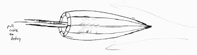
I was encouraged by the fact that they were able to snake a smaller pipe into the larger one and siphon off some of the oil. So the idea is to snake a small, streamlined device up the pipe, and then when you pull the "rip cord" it expands to to fill the entire pipe, gripping at the sides. It reminds me of something you would find on Batman's utility belt. The idea is to use the pressure of the fluid flow, transferred by a linkage (a lever) to push against the wall of the pipe. Then, of course, you need something strong to fill the body of the pipe. For that there are a couple of different options, but the main idea is to use Kevlar cloth, which is flexible, but has incredible tensile strength. (It's the stuff they use to make bullet-proof vests.)
So here is a picture of the device when it's all packed up:
Here is what it looks like when it's deployed:
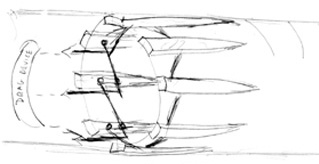
The darker lines are the linkage which pushes the feet out. Each pushes away the one next to it, around the circle. The process could be started with an elastic cord in the foot to pull a sliding mount rearward toward the fixed mount, but the real force comes from pulling on the end of the linkage arm. Longer is better, as this is a lever, but you can't go too long or it won't fit in the closed package and/or it will bump up against the pipe wall.
In the diagram the ends of the linkage are connected to the blob at the left marked "Drag Device", which I imagine could either be a parachute made of kevlar, designed to fill the entire pipe cross-section, or an umbrella framework fitted with kevlar cloth. I can see benefits of both alternatives, but the main point is that it's something that spreads out to cover the entire cross section of the pipe, and it's connected to the lever arms so as to drive the feet into the wall of the pipe to anchor the whole thing in place.
So where does this go wrong? A weak point in the design is the linkage arms, which will be subject to a huge amount of shear force. The size of the shear force will determine the required width of the linkage bar, so let's estimate what's needed. The numbers I came across in the press are that the main pipe is 21 inches across, and that the pressure due to the flow in the pipe is on the order of 6,000 to 10,000 psi. If you put the radius 10.5 inches into the formula for the area of a circle, πr2, you get an area of about 346 in2. Multiply that by 6,000 psi and convert 2000 lbs = 1 ton gives a total force of about 1040 tons! That explains why they can't just drop a heavy weight into the hole to plug the leak. The force of the fluid is more than enough to lift anything less than 1040 tons, and that doesn't even take into account the buoyancy due to being under water.
In fact, this lets us estimate how much drilling fluid ("mud") they would need to insert in the well bore for a successful top kill. If we estimate the density of mud [1] at about 1200 kg/m3 then we need a volume of mud which has a weight equal to 1040 tons. Converting to metric, that's about 943,500 kg (or 943 Mg - Mega not milli!). And using 21 inches as the inside diameter of the bore, it works out to a column height of 3520 meters. Converting that to feet gives about 11,500 feet. Wow.
I think I remember seeing a graphic that showed the depth of the well to be 18,000 feet below the sea floor, which means that the top kill was at least possible. But that means that the bore, which is just over 3 miles deep, had to be filled with mud to at least a height of 2 miles to stop the flow. No wonder it was difficult.
Back to my device. If there are 8 segments then to stop the flow each of them will have to hold a force of 1/8 the total, which is about 130 tons. And that will be as shear force on the end of the cross link. From that we can compute the required diameter of that cross link. The quantity we need to know is called the "ultimate strength" of the material the object is made of, which measures the force (per cross section) at which the object will break. In general metal is weaker against shear force than it is against tension, and for steel the "ultimate strength" for shear is about 75% of the ultimate tensile strength[2]. The tensile strength of steel can vary a lot depending on the alloy, but for estimation it seems reasonable to use the value 400 × 106 N/m2, which I got from a freshman physics textbook (Halliday, Resnick, and Walker, 6th Edition, pg 285), or 440 × 106 N/m2, which I got from Wikipedia[3]. Since 130 tons is about 1.16 × 10⁶ N the cross-sectional area of the linkage arm has to be 3.5 × 10⁻³ m2. And if we assume a circular cross-section then the diameter has to be about 6.7 centimeters, which is about 2.6 inches. So those cross-links have to be much thicker than a regular crow bar or they will just shear right off.
Another way to look at this is to imagine that we wanted to build a simple grating to go over the pipe opening (perhaps to catch pieces of old tires and golf balls?). Then if the grating is anchored at the sides in 8 places, each anchor, if circular, would have to have a diameter of 2.6 inches, if it is going to be able to hold back the entire flow.
That may not be a problem, but remember that this all has to pack up into as thin a cross section as possible. Even if the cross-bars were 1/8 of a cylinder (like pieces of 8!) the entire cross section of all 8 bars would have a diameter of about 7.5 inches. Add to that the thickness of the feet, which is likely to be at least an inch of steel, and you are up to a diameter of about 10 inches. In a pipe that is 21 inches across, that is a significant amount of the total cross section.
From this we can then estimate the force required to push this thing into the pipe, as well as the diameter of the pusher rod. The cross-sectional area for a diameter of 10 inches is about 78.5 in2. Multiply that by 6000 psi and divide by 2000 lbs per ton and we get the force required in tons to push a flat plate against the flow. But with streamlining the drag force could be a lot less. A good coefficient of drag is 0.5, meaning only half the full-on force is actually required. So let's be optimistic and assume that. Overall, it would then take about 120 tons of force to push this thing along into the pipe against the flow.
That's close enough to the 130 tons of tensile strength required of the cross-links, so we can estimate the cross section of the pusher rod to be at least 2.5 inches. That's if it is solid steel, but if it's hollow then it would have to be larger.
I had hoped to keep the diameter of the device under 6 inches, just because I had heard that the gauge of some of the smaller pipe they were using was just over 6 inches, and so it might make it possible to deliver this thing by inserting it into such a pipe. So let's run the numbers for a 6 inch diameter. Multiply 6,000 psi by πr2 with r=3 inches, then by 0.5 for the coefficient of drag, and then divide by 2000 lbs/ton. The result is about 42.5 tons. That's around one third of the force required for the 10 inch diameter, so it really is a significant improvement.
Now whether it is 120 tons or only 40 tons, the insertion force has to be provided by some kind of mechanical device. They can't just stack lead bricks on top of it until they get enough weight. I do not know if the equipment they have available is capable of such forces, or if this is way out of the range of possibility.
Keep in mind that the estimates we have used have all been "optimistic". We've used the lower value for the pressure, 6,000 psi, rather than 10,000 psi. And we've used the "ultimate" strength of the steel, but it would bend at a lower force, called the "yield strength". On top of that, the device would likely experience greater forces when first deployed than the "steady-state" forces needed to hold it in place for the long term. So this is all based on a "best case" scenario that likely underestimates what it would really take. I liked the idea at first, but now I'm skeptical that it would really work.
So to summarize: It would take a force of 1040 tons or more to stop the flow of oil out of the pipe. Trying to stick something into the pipe which could expand to form a plug would take on the order of 120 tons of force, which is a big reduction, but still a huge force. If you could make the device small enough to fit into a 6 inch pipe it would still take on the order of 40 tons of force to push it into the larger 21 inch pipe against the flow of oil.
To me these numbers all seem fantastical. What I take away from all this is a better appreciation for the size of the forces involved. Holding back the flow of oil would require beams of steel several inches across, and forces in the range of 100 tons or more for each beam. On top of that, it would have to be inserted using powerful hydraulic machinery which is controlled remotely from the surface. This is clearly not an easy engineering problem to solve, and I appreciate that more from having thought this through.